Microscope configuration setup
Before creating an experiment or importing results from HKL Channel 5 or TSL OIM, a microscope configuration must be created. The microscope configuration defines:
- the dimensions of the EBSD camera
- the position of the EBSD camera in the microscope
- the tilt axis of the sample
These information are required for the operations of the experiment. The following paragraphs gives more detail on how to setup the microscope configuration.
Dimensions of the EBSD camera
The dimensions of the EBSD camera refer to the width and height of the camera in unit of length (e.g. mm). If the camera is circular, the width and height are equal and are equivalent to the diameter of the camera. This information is required to calibrate the pixels of the diffraction patterns.
Todo
How to measure the dimensions
Microscope coordinate system
The microscope coordinate system is the default coordinate system of EBSD-Image to position the EBSD camera, the sample, the Kikuchi bands, etc. in space. The position of the EBSD camera and the tilt axis of the sample must be expressed in this coordinate system.
The microscope coordinate system is orthogonal. The z-axis is defined to be parallel to the electron beam and pointing towards the electron column. The x-axis and y-axis do not have any particular direction except to be at 90 deg from the z-axis and at 90 deg from each others. The origin is located below the pole piece, such that a sample located at a working distance of 15 mm has the coordinate (0, 0, -15) mm.
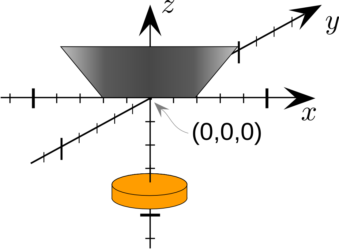
Microscope coordinate system.
The position of the camera is defined by two vectors:
- \(\vec{n}\): vector normal to the camera screen pointing away from the sample
- \(\vec{d}\): the vector parallel to the x-direction of the camera (i.e. parallel to the camera’s width)
The tilt axis is also defined as a vector (\(\vec{t}\)). The direction of the vector is important as it determines in which direction of the tilt. Using the right hand rule, if the thumb is along the tilt axis, a positive tilt angle will follow the motion of the fingers. Note that the tilt axis vector is in most cases parallel to the x vector of the camera.
As an example, the following figure gives a schematic representation how the vectors are determined from this particular microscope configuration.
- \(\vec{n} = (1, 0, 0)\)
- \(\vec{d} = (0, -1, 0)\)
- \(\vec{t} = (0, 1, 0)\)
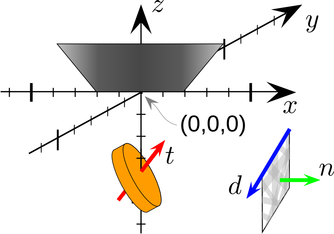
Example of a microscope configuration.